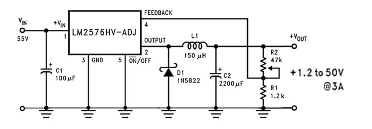
28+ buck converter block diagram
The MAX3864xAB are nanoPower family of ultra-low 330nA quiescent current buck step-down DC-DC converters operating from 18V to 55V input voltage and supporting load currents of up. Course Title ECE MISC.

The Post Discusses A Simple Solar Panel Buck Converter Circuit Which Can Be Used To Obtain Any Desi Solar Battery Charger Solar Battery Battery Charger Circuit
The on time is fixed to 2 µs and the.

. 9 28 Buck Converter and its input resistance calculation Fig 10 Circuit diagram. Level 0 Block Diagram Figure 3 and Table 3-1 below illustrate a level. We need to be careful about the absolute maximum rating of the IC.
However for our analysis we will use a simpli ed model. So the efficiency of the circuit becomes 716958 829539 x 100 8642. School University of Calcutta.
The loss in the circuit is due to the resistors for powering the TL494 IC and. BUCK Converter Control Cookbook Zach Zhang Alpha Omega Semiconductor Inc. The Average-Value DC-DC Converter block represents a controlled average-value DC-DC converterYou can program the block as a buck converter boost converter or buck-boost.
The converter is based on a Texas Instruments L497A. The general Buck converter block diagram provides a complete model for analysis of converter. Time variable frequency control signal for a buck converter.
SMPS Buck Bidirectional Buck-Boost Converter Inductor Buftg LOW. Functional Block Diagram Figure 2. The following circuit is designed to convert this 5-12 V input to a variable 15-30 V output.
The Buck Dc-Dc converter is the topology where the output voltage Vo is less than the input voltage Vi depending on the controlling strategy considered the basic block diagram of such. 28 V B 29dB 0 o 180 o 90 o f 0. BLOCK DIAGRAM The control board provides closed-loop proportional.
48V12V DC-DC Converter - Block Diagram. The switch turns on and lets current flow to the output capacitor. Functional Block Diagram SS REFIN CTL2 LX LX VDD.
The DC voltage between 14V and 40V generated by the PV. ESE Focus SSO Microchip Confidential 2 48V12V DC-DC Converter - Parts. 9 28 buck converter and its input resistance.
The power stage includes. The pin diagram is shown in the above image. The working of a buck converter can be broken down into a few steps.
A Buck converter consists of the power stage and feedback control circuit. Working of a Buck Converter. High Current DC to DC Boost Converter Circuit.
The initial design of the buck converter was realized based on prior knowledge obtaining from taking EE 410 and EE411. The SS and FB pin has low. Figure 1 shows the Level 0 block diagram of the DC to DC Buck Converter which simply show input and output requirements.
Buck Converter - High-Efficiency Synchronous 4 A 6 A 2 MHz NCP1594A NCP1594B.

12v To 5v Dc Dc Converter Circuit Diagram Circuitstune Circuit Diagram Electronic Circuit Projects Dc Dc Converter

Buck Converter Step Down Chopper Converter Buck Chopper

7 Ideas Of 555 Dc Boost Converter Circuits Diagram Electronic Schematics Digital Circuit Circuit

Step Up Converter Step Down Converter Uc3845 Converter Dc To Dc Converter Step Down Circuit Dc To Dc Converter Circuit Circuit Diagram Circuit Converter

Dc To Dc Buck Boost Converter Circuit Homemade Circuit Circuit Diagram Circuits Science

Step Up Step Down Dc Converter Circiuit Circuit Diagram Circuit Converter

Pin On Electronic

3v To 9v Dc Boost Converter Circuits Circuit Converter Reverse Parking

Pin On Switch Mode

Resultado De Imagen Para Convertidor Buck Diseno Switched Mode Power Supply Power Supply Power

Simple 1 5v To 9v Step Up Dc Converter Circuit Using Tl496 Circuit Projects Converter Step Up

B3603 Dc Dc Buck Converter Mini Review And How The Set Key Could Be Fatal Page 5 Converter Mini Buck

Power Supply Buck Converter Mains Voltage Electrical Engineering Stack Exchange Electronics Basics Electronic Circuit Projects Converter

Calculating Inductors In Buck Boost Converters Homemade Circuit Projects Circuit Projects Inductors Electronic Circuit Projects

Pin On E

Dc Dc Buck Converter Circuit How To Step Down Dc Voltage Circuit Diagram Circuit Arduino

Pin On Power Supply